

Bath Abbey Footprint Project Hot Spring Water Heat Recovery
Posted on: December 2018Neil Francis, Burro Happold
Bath Abbey's New Sustainable Heating System
About the author:Neil Francis is an Associate Director at BuroHappold Consulting Engineers in Bath. BuroHappold is an international, integrated engineering practice founded in 1976 by the late Sir Ted Happold. Today the practice employs over 1700 staff in 21 offices around the world offering all the key disciplines associated with the built environment and consulting. Neil’s discipline is Building Services and Environmental Engineering with over 25 years’ experience working in particular on Cultural and Civic projects.
See www.burohappold.com for more information.
Over one million litres of natural hot spring water at up to 45°C rises in the centre of Bath every day, flowing through the Roman Baths and the Great Drain to discharge into the River Avon. Bath Abbey plans to recover energy from the water in the Great Drain for heating of the Abbey as part of the much broader £20m Footprint Project currently underway on site.
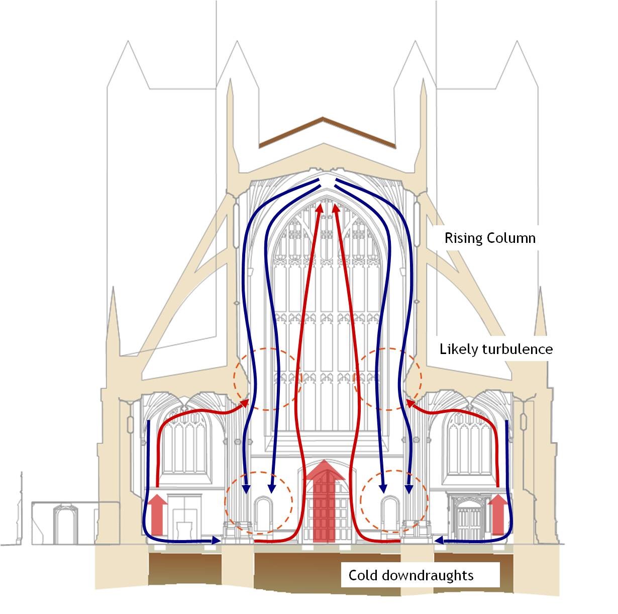
The Footprint Project is about carrying out essential repairs and improving facilities for future generations. In the Abbey in particular, there are over 8,500 burials below its floor, many of which have collapsed making the floor structurally unstable. Furthermore, the Abbey's existing heating is over 100 years old and at the end of its useful life, with comfort issues and excessive cold down-draughts from the large areas of glazing.
 |
 |
|||
|
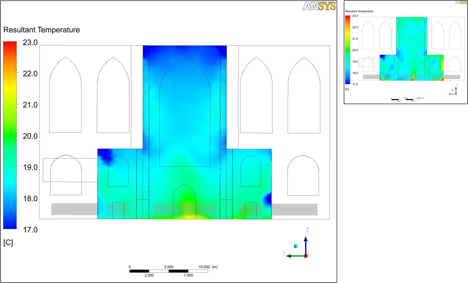
Fig 2. Abbey thermal analysis showing proposed underfloor heating and realigned trenches giving more comfortable and uniform low level occupied zone conditions, compared to existing heating (inset). |
In terms of the new heating in the Abbey, early design stage studies quickly identified underfloor heating as the preferred background heating solution, with supplemental trench heating for colder days. Underfloor heating is ideal to connect to ‘low grade’ alternative energy sources, being able to operate efficiently at lower temperatures and provide beneficial radiant heating to the low level occupied zone in the large volume Abbey space.
Later dynamic thermal modelling and CFD (computational fluid dynamic) studies of the whole Abbey space allowed the design to be further refined, particularly confirming the Nave trench heating realignment from directly below the side windows to the centre to reduce large scale convective currents.
 |
 |
|
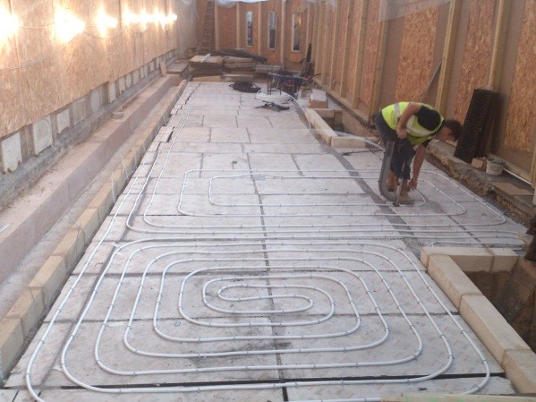
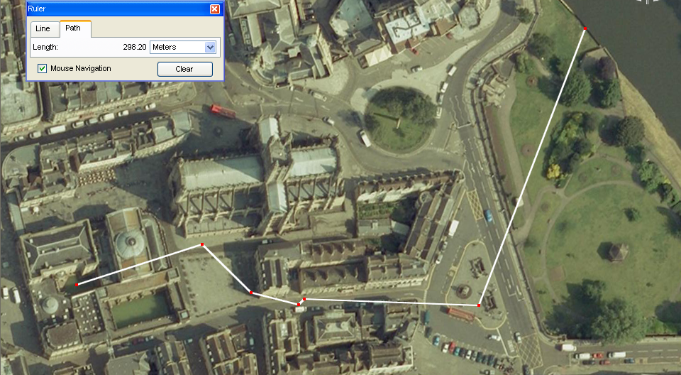
| Fig 3. Abbey floor trial to test proposed floor stabilisation, underfloor heating, and ledger stone repair methodology. | Fig 4. Route of Great Drain showing main source in the Kings Bath in the Roman Baths (to the left), flowing though the Great Drain below the streets of Bath, and finally discharging in the River Avon (to the right) just downstream of Pulteney Bridge and the Weir. |
In terms of the Bath hot spring water, this rises naturally to a number of springs and boreholes in the centre of Bath. The water is very constant with a temperature of approx. 45°C and a flow rate of approx. 14 litres per second, equating to over 1.2 million litres per day. The main flow is into the Kings Spring in the nearby Roman Baths which in turn flows down the Great Drain alongside the Abbey at depths of up to 7m below street level at a reduced temperature nearer 36°C.
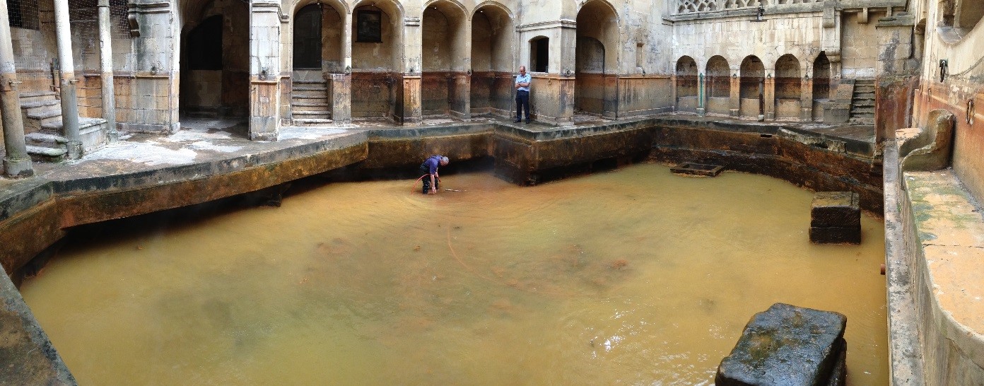 |
| Fig 5. Kings Spring in the Roman Baths Complex as the main source of the water flowing in the Great Drain. Photo showing Kings Bath drain-down to clear algae, silt, and other debris build-up. Kings Spring arises though the gravel bed of the Kings Bath. |
Historically the water was used for bathing and its perceived healing properties. However technically the water is difficult to use due to high minerals and silt content, dissolved oxygen and risk of corrosion, and health risks from ‘pathogenic amoeba’. A number of ‘open-loop’ (pumping the water directly) and ‘closed-loop’ (pumping indirectly) heat exchange options have been considered, with only closed-loop considered a viable long-term robust and maintainable solution.
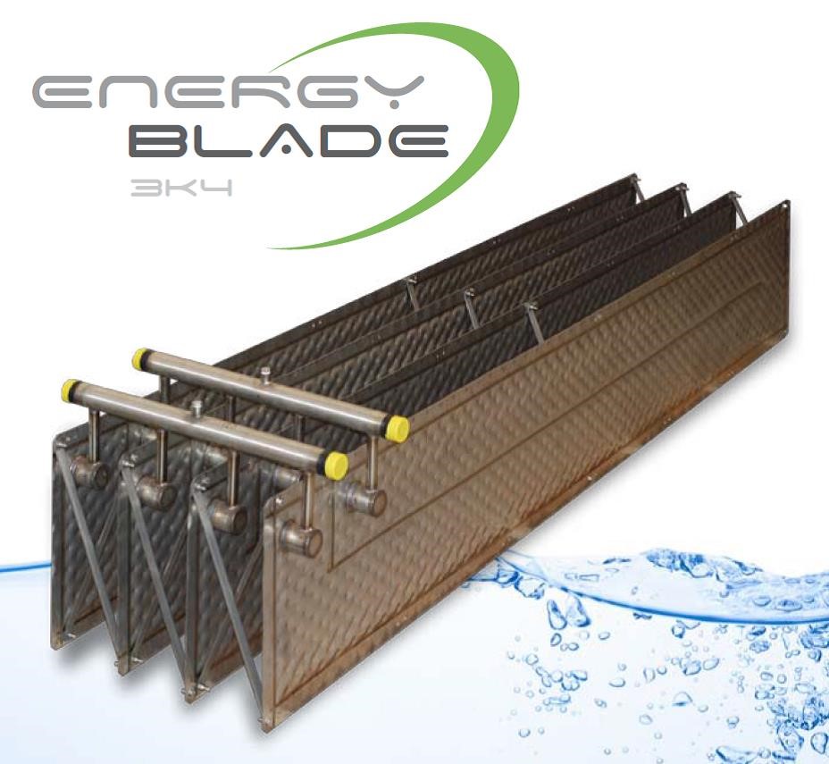
The proposed closed-loop solution is to use ‘Energy Blade’ stainless steel heat exchangers submerged in pairs in series along the length of the Drain to extract up to 160kW of energy. The heat exchangers will provide water at nominally 25°C to the Abbey electric heat pumps that will raise the temperature further to 50-55°C, suitable for underfloor heating throughout the heating season, and trench heating during milder weather. Conventional gas-fired boilers will supply water to the trenches at 80-85°C during cold weather, as well as providing back-up to the heat recovery system generally.
 |
 |
 |
 |
|||
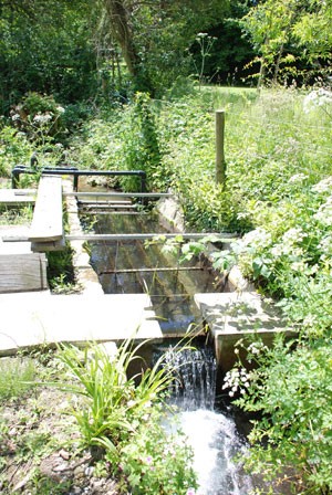
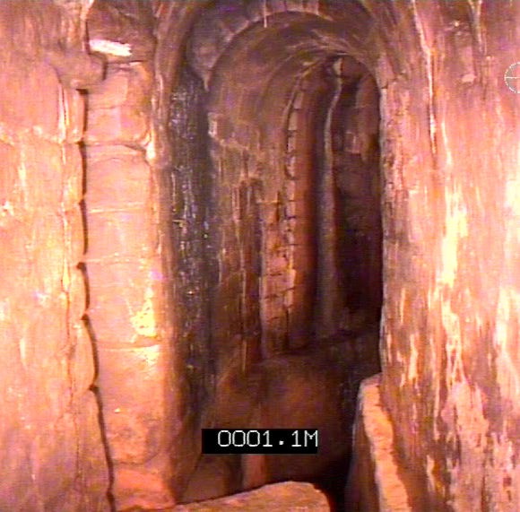
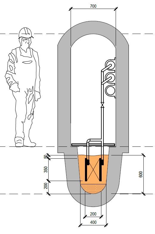
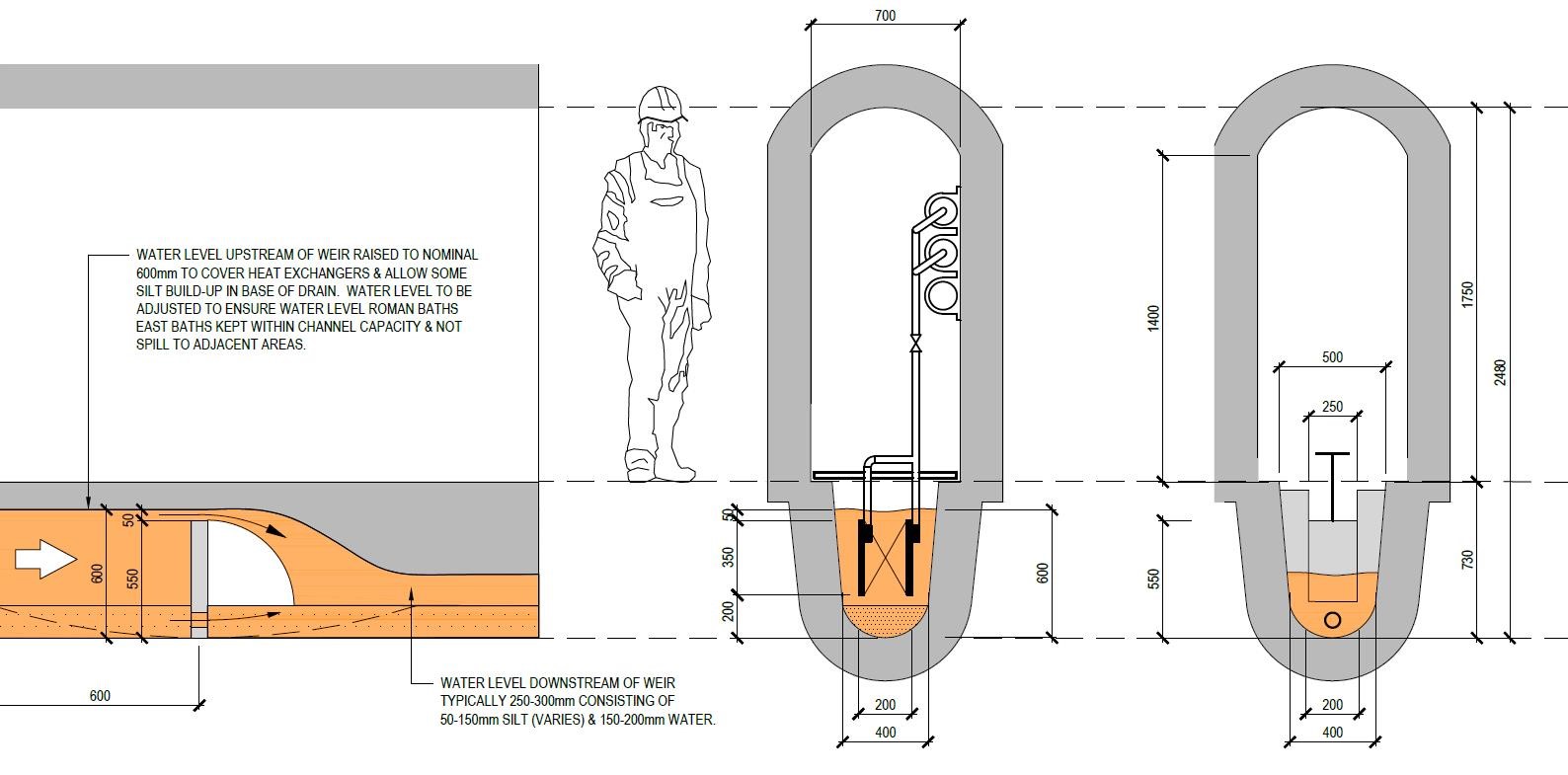
| Fig 6. Energy Blade ‘closed loop’ heat exchanger example 4-blade bank. The Abbey will use pairs of blades in series in the Great Drain to fit in the narrow channel. | Fig 7. Energy Blade example surface water installation in flow stream with weir to raise water level. | Fig 8. Great Drain with water flowing at low level in invert of channel 7m below York Street. Note raised walkway ledge along sides for access. | Fig 9. Preliminary design drawing showing pair of Energy Blade heat exchangers submerged in raised water level in the Great Drain. | |||
 |
||||||
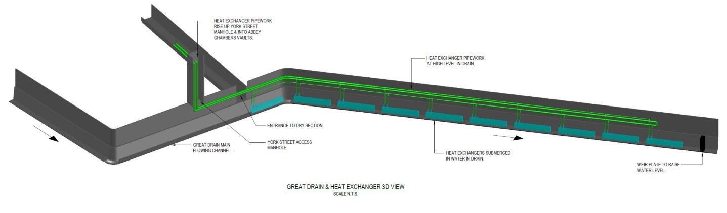
| Fig 10. 3D view of Great Drain below York Street showing new weir plate (to right) and nominal 10nr pairs of Energy Blades (total 20nr) submerged in raised water level. | ||||||
Numerous trials, investigations, and mock-ups have been carried out in the Great Drain. Any works in the Drain are a challenge due to approvals, difficult access, confined space working, and high temperature and humidity environment.
One important consideration is that the water flow in the Great Drain is only about 150-200mm deep. Hence a key series of investigations during the design stage, carried out over a month-long period, were to investigate water flows and temperature, to install a mock-up pair of heat exchangers, and to install and refine a mock-up weir design to raise the water level in the Drain sufficient to submerge the heat exchangers whilst not flooding the upstream Roman Baths.
Further complexities have included working in a scheduled ancient monument area, archaeological investigations, obtaining numerous consents, and creating a new licence agreement between the Local Authority and the Abbey. Environment Agency approval has not been necessary as only heat energy is being removed from the water, not the water itself, so not changing the overall flow rate.
The Footprint Project design started in earnest in 2010. The project finally started on-site recently in Summer 2018 and should be complete around the end of 2020. Heat recovery works in the Great Drain should commence in early 2019 with heat recovery starting later that year allowing time for commissioning and fine-tuning.
A similar scheme is also being developed in the Roman Baths to extract 80kW of energy - the Abbey and Roman Baths projects being deliberately separate but still mutually compatible.
 |
 |
|||||
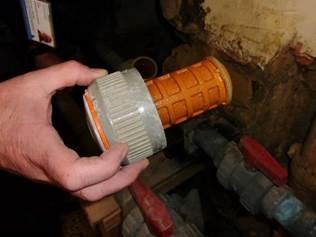
| Fig 11. Roman Baths hot spring water fountain showing silt, scale, and algae growth in the daylight. | Fig 12. Roman Baths abandoned heat recovery system filter showing silt build-up causing complete blockage. | |||||
 |
 |
|||||
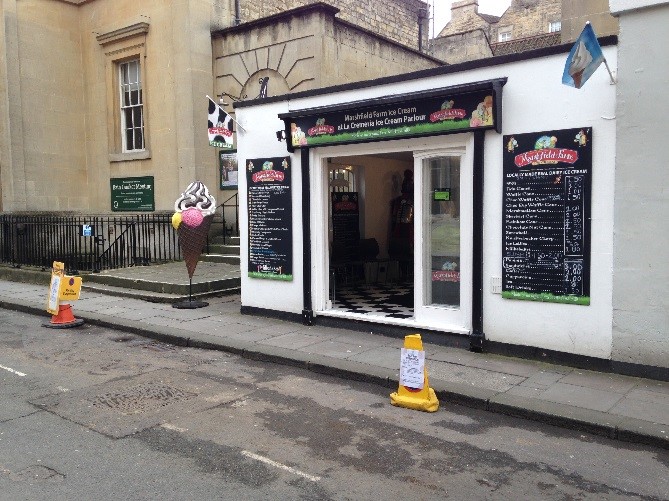
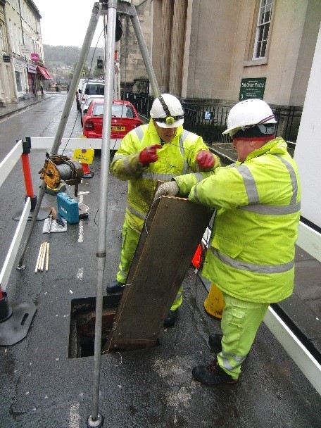
| Fig 13. York Street access manhole in parking bay outside ice cream shop showing typical parking bay closure arrangement. Temporary barriers required around area during works. | Fig 14. York Street access manhole typical tripod and winch set-up for man access, and for all equipment and materials, during installation as well as for maintenance and future replacement. | |||||
 |
 |
|||||
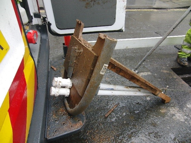
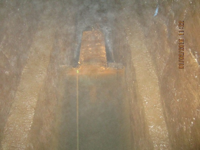
| Fig 15. Weir plate plywood mock-up showing rectangular overflow and orifice underflow. | Fig 16. Weir plate mock-up in Drain channel with view looking downstream. Note high humidity steaming up camera. | |||||
 |
 |
|||||
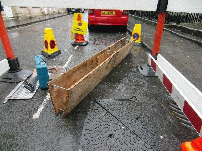
| Fig 17. Plywood mock-up of pair of 2400x350mm Energy Blade heat exchangers. Heat exchangers slightly angled for mock-up, but subsequent design based on completely parallel. | Fig 18. Great Drain below York Street typical view. | |||||
 |
 |
|||||
| Fig 19. Extract from work in progress design drawing showing the weir plate preliminary details. | Fig 20. Extract from preliminary design drawing showing a pair of Energy Blade heat exchangers submerged in raised water level in the Great Drain. | |||||
The Water Efficiency (WATEF) Network
©2026 All rights reserved
Website design by